The number one reason I started this blog was to provide help and encouragement to new and prospective Network Engineers. Most of the time, I’ll be passing on experiences that I have in the field of networking. However, as I have time, I also want to post articles that I hope will take your understanding of networks up to the next level. I will include practical examples and exercises you can do at home which will give you a better understanding of networks, and I hope will make you a better Network Engineer. Today is my first post of this type. Please let me know if this is helpful (or not). Here goes…
The OSI Seven Layer Model. (I can you see wincing!!) Why bother, right? Most people I know learned just enough about the OSI model to answer the questions on some written test, and most likely have not given it a thought since. It’s just a bunch of theory, and doesn’t really help in the real world. Well, if that’s what you think, then you are missing a powerful tool in understanding networks AND in troubleshooting them. The best network engineers know the OSI model. And you can too.
I’m not going to bother going over the OSI model…there are plenty of articles on the web that do that already (remember, Google is your friend). But what I will do is prove that the OSI model is real, and you can see it in action. And all it takes is our friend PING.
Open up a DOS window on your PC (or a terminal shell on Linux), and ping your default gateway (on my home network, my default gateway is 192.168.77.1)…it should look something like this…
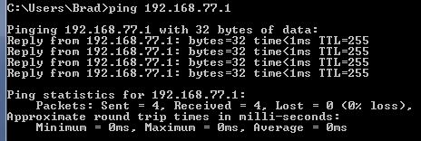
PING example
How does PING work? Basically, PING is a utility which is part of the TCP/IP suite of protocols. When you run PING, it creates an ICMP packet and starts a timer (so it will know how long the reply took to get back). More specifically, it creates the packet and inserts the layer 3 header (destination and source IP addresses), starts the timer, and then drops it down to layer 2 (Data Link) where the MAC header (source and destination MAC addresses) are added. The packet is then dropped onto layer 1 (physical) and the packet is off and running. When the packet returns, it works it’s way back up the stack, and the PING utility stops the timer and prints out the results. In the above example, it performed this four times.
Now, lets do this again, but we want to ping something on your local network that your PC has not seen yet. For most people, a good idea would be to ping your smartphone or printer or boot up another PC and ping it. Ping that IP address in the DOS window….you should see something like this…
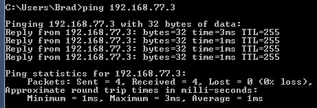
PING example first time
Do it one more time…
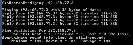
PING example second time
Now, take a look at these two examples and see what the difference is. It’s not major, but it is there. Notice in the first example, it took 3 ms for the first reply to return, but only 1 ms for the other three replies. In the second example, all four replies were just 1 ms. Why?
It’s now time for you to become the packet…I call it “Be the Packet”. Pretend you are the packet and follow the flow of the packet…
First step: PING creates the packet, applies the IP header and starts the timer. Easy enough.
Second step: The packet is dropped down to the MAC layer, where the MAC address header is attached. It needs to insert the destination and source MAC addresses…the source is easy, but where does it get the destination MAC address? That’s right…it has to ARP for it. (ARP – Address Resolution Protocol. Remember, Google is your friend.) So there is a slight pause while ARP gets the destination MAC address (this is Layer Two in action!!)…and remember, PING has already started the timer. When the MAC address is received via ARP, it’s added to the MAC header and dropped down to layer 1.
Once the PING reply is received, it is passed up the stack to the PING utility, and the timer is stopped. In the first example, it took 3 ms, which included waiting on the ARP request. The rest of the replies were quicker because the computer already knew the MAC address of the destination and did not have to look it up again. There is a table that TCP/IP maintains called the ARP cache…you can see it in Windows by using the “arp -a” command (“arp -n” in Linux). If you looked at the ARP cache before you ran the first PING test, it would have looked like this…
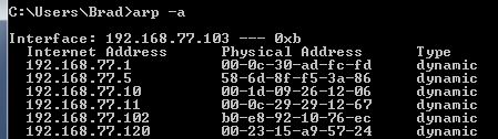
ARP example first time
Notice there is no entry for 192.168.77.3. Here is the ARP cache after running PING…
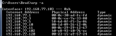
ARP example second time
Now the ARP cache has an entry for 192.168.77.3…you can see it’s MAC (Physical) address is
00-0c-ce-7a-33-80. After the first PING, all of the remaining pings were able to skip the ARP request, and send the packet on through, saving time.
SUMMARY: Hopefully, the above example helped you see one of the seven layers in action…layer two in this case. As you learn more about networking and how protocols work, you will start to develop a sense for what layer controls what. And with that, a better understanding on how to troubleshoot issues.
And yes, I know this post required some thinking…but understand, being a Network Engineer will require lots of thinking all the time. I mean, they are not going to pay you good money just to be a bump on a log…right?
Good post. Every network engineer has to know why that first packet gets dropped ( or high delay) as opposed to the rest of the three replies.